How Do You Make a Continuous Profile in Solidworks
SOLIDWORKS Loft Feature
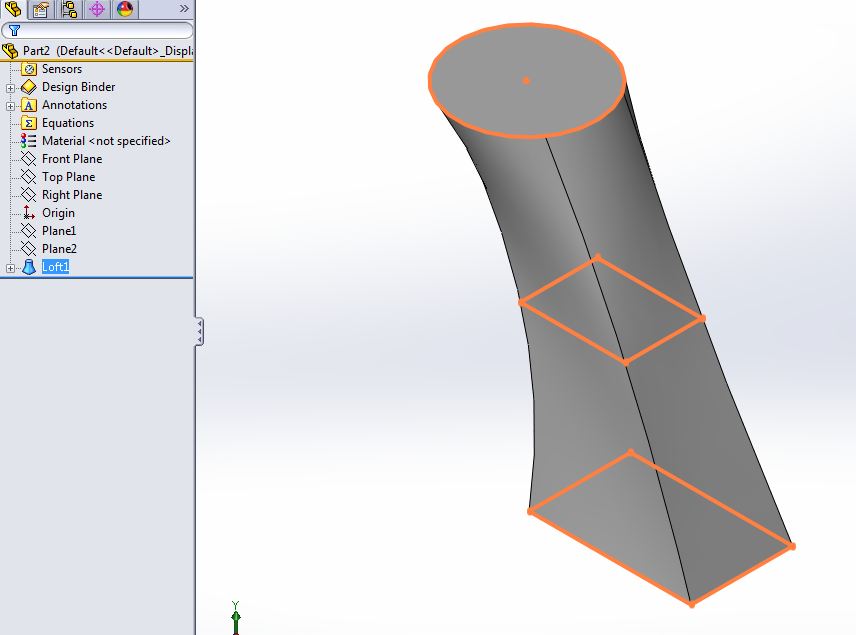
Figure 1: Example of Loft created with 3 sketch profiles.
There are several features in SOLIDWORKS that work well for creating smooth and organic shapes. One of these is the Loft feature. We are going to take a close look at the loft options and how to use them to control a loft feature's behavior. While we will be using the Loft feature to create solid geometry, it can also be used to generate surface geometry.
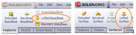
Figure 2: Solid Loft and Surface Loft tool buttons.
The loft feature in SOLIDWORKS allows you generate complex geometry in a single feature. It does this by interpolating surfaces between various cross-sections of a model. These cross-sections can be sketches, faces, or edges. In the loft interface, these cross-sections are considered "Loft Profiles". Because this SOLIDWORKS tool is interpolating surfaces to create geometry, it can be difficult to control the loft enough to produce the desired geometry. Here are some tips and tricks for using the Loft feature.
Selection location and Connectors
The most basic method of controlling the loft involves being specific about the location you click when selecting your profiles. It does matter where you click. When solving the loft geometry, SOLIDWORKS attempts to line up the loft profiles based on the entities you choose. If you select an endpoint of a line in the first sketch profile, it is best practice to also select the corresponding point for the second profile that should be "connected" to this first selection. In the image below, you can see how the top portion of this geometry might twist depending on the selection location of the upper profile.
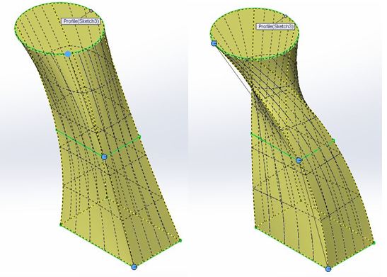
Figure 3: Connectors control how SOLIDWORKS interpolates between the Loft profiles.
The connected blue dots are called "connectors". They make it easy to identify the locations on the profiles that SOLIDWORKS is using when interpolating between them. You can drag these connectors to further adjust, and have more control over, the geometry produced. If you right click on this preview, and select "Show All Connectors" several more connectors will appear. All of these dots can be positioned independently to adjust the loft results.
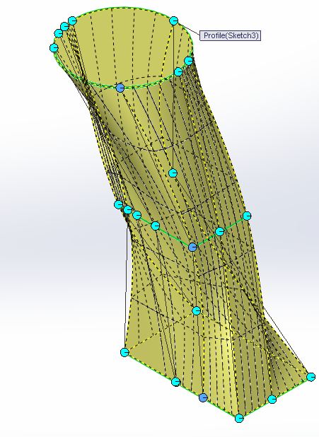
Figure 4: Using the option "Show All Connectors" reveals additional connectors for adjusting the loft's geometry.
Sketch Considerations
When using the SOLIDWORKS Loft feature, it is a best practice to make sure the loft profile sketches have the same number of segments. In the images above, 2 profiles are rectangles and the upper profile is a circle. SOLIDWORKS can easily transition between the rectangles by essentially connecting the 4 corners. It is less predictable how it will transition from the rectangular to the circular profiles. The connectors are likely to introduce some degree of twist in this portion of the solid. Just like the four lines making up the rectangles shown below, we would rather have 4 arcs making up the circle.
After the circle is sketched, the "Split Entities" sketch tool will allow you to break the circle up into multiple, co-radial, arcs. In the image below, the circle now consist of 4 connected arcs. Dimensioning these arc endpoints will give you much more precise control over how SOLIDWORKS interpolates between the various Loft profiles.
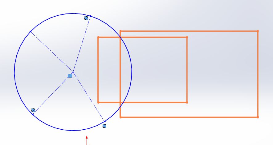
Figure 5: Use the "Split Entities" sketch tool to ensure all loft profiles contain the same number of segments.
Start and End Constraints
Loft features have some similarities to the Splines found in SOLIDWORKS sketches. When you sketch a spline, SOLIDWORKS generates the geometry by interpolating between the spline points. This is similar to how a loft interpolates the solid geometry between the loft profiles. In the sketched spline, you have "Spline Handles" that exist at each spline point. These handles give you the ability to control the "weight" and direction of the spline at each point.
Loft features have similar options called "End Constraints". As the name implies, these are only available for the beginning and ending loft profiles. In the image below, you can see the "Normal to Profile" setting is applied in the example on the right. This setting gives more "Weight" to the profiles causing the geometry to more closely match the profile's shape at the start and end of the loft.
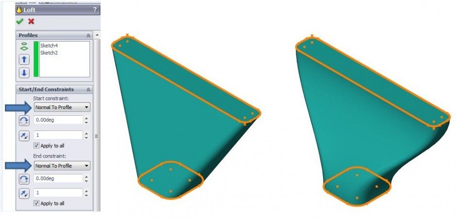
Figure 6: Using the Start/End constraints parameter.
Using Guide Curves
Using a guide curve to control your loft will allow you to have much more precise control over the geometry generated by the feature. A guide curve defines the path that the loft takes as it interpolates between the loft profiles. This parameter acts very similar to the "Path" sketch available when creating a Sweep feature in SolidWorks. This guide curve can be a single sketch or several different sketches can be used to define multiple guide curves. In the example below, a single guide curve is being applied to the same loft feature from the previous examples.
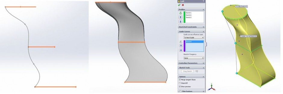
Figure 7: Using a Guide Curve can provide the most control over the Loft feature.
Through the use of these techniques, you can achieve more precision over the geometry created from the SOLIDWORKS Loft feature.
Greg Buter
Application Engineer Manager
Computer Aided Technology, Inc.
Interested in Learning More About SOLIDWORKS? 
CATI offers a variety of introductory and advanced training courses that are available both in-person and online to fit around your busy schedule. Schedule your training today!
View All SOLIDWORKS Training >>
Source: https://www.cati.com/blog/tips-and-tricks-for-using-the-solidworks-loft-feature/
0 Response to "How Do You Make a Continuous Profile in Solidworks"
Post a Comment